Типичная история: человек покупает ADXL345, лепит его на хотэнд, гоняет SHAPER_CALIBRATE, получает красивый график — и печать не становится лучше. Через неделю он протягивает ремень, и весь расчёт можно выбрасывать: частота уехала.
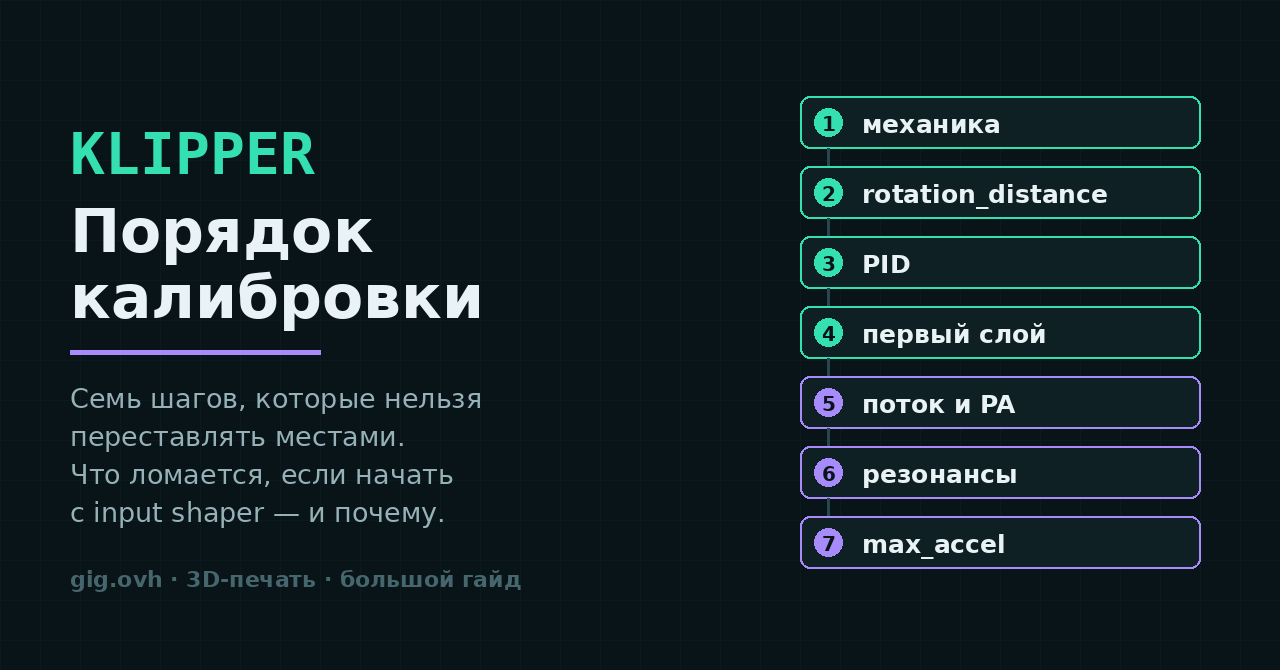
Klipper даёт десяток инструментов калибровки, и почти все они дают правдоподобный результат независимо от того, готова ли машина. Именно в этом ловушка: цифра появляется всегда, но смысл она имеет только если то, что под ней, уже зафиксировано. Ниже — последовательность из семи шагов и объяснение, почему у каждого шага именно такое место.
Правило одно: калибровка измеряет следствие. Если причина ещё гуляет, измерение придётся повторять. Поэтому порядок идёт снизу вверх — от железа к софтверным компенсациям, а не наоборот.
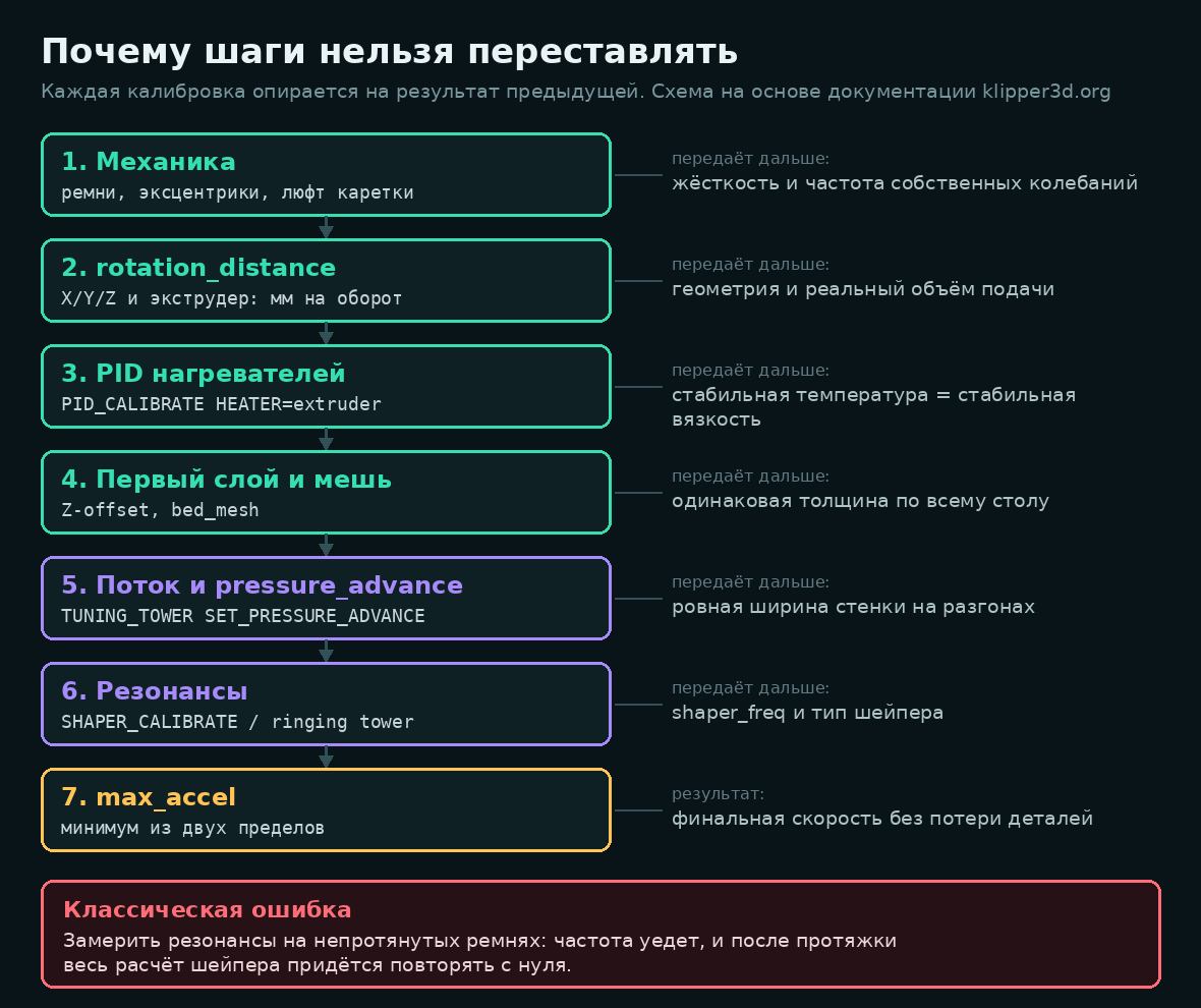
Схема на основе документации klipper3d.org
Шаг 0. То, что делается до любой калибровки
Официальная документация Klipper начинает не с настроек качества, а со списка проверок безопасности — и правильно делает. Ни одна из них не про печать, но каждая может стоить принтера.
- Температуры. Графики сопла и стола показывают комнатную температуру и не растут сами по себе.
M112. Аварийная остановка должна переводить прошивку в состояние shutdown;FIRMWARE_RESTARTвозвращает её в норму, температуры продолжают обновляться.- Нагреватели. Задайте соплу 50 °C — температура должна расти в течение ~30 секунд. Выключите — за несколько минут вернуться к комнатной.
- Enable-пины. После
M84все оси должны двигаться руками. Если моторы заблокированы — в конфиге нужен инвертированный пин:enable_pin: !PA1. - Концевики.
QUERY_ENDSTOPSпри отведённых осях —open, при нажатом вручную —TRIGGERED. Инверсия — тем же!. - Направление моторов.
STEPPER_BUZZ STEPPER=stepper_xдёргает ось на 1 мм десять раз. Проверяем направление, возврат в исходную точку и саму дистанцию. - Экструдер. Прогреть до рабочей температуры, нажать «Extrude», убедиться, что мотор крутит в правильную сторону.
Пропускать пункт 2 нельзя ни при каких обстоятельствах. Неработающая аварийная остановка — единственный отказ из этого списка, который заканчивается не испорченной деталью, а пожаром.
Шаг 1. Механика: то, что нельзя починить конфигом
Здесь нет команд Klipper, и именно поэтому шаг чаще всего пропускают. Между тем всё, что будет измеряться дальше, — производная от жёсткости конструкции.
Что проверяется: натяжение ремней X и Y (одинаковое, без «струны» и без провисания), затяжка шкивов на валах — винт должен стоять на лыске, а не на круглой части, люфт кареток и эксцентриков, затяжка рамы, отсутствие качания стола.
Почему это первым: собственная частота колебаний рамы и каретки — то, что вы будете измерять на шаге 6. Она напрямую зависит от натяжения ремня и массы каретки. Протянули ремень после калибровки шейпера — получили другую частоту и старые коэффициенты.
Есть удобный побочный инструмент: TEST_RESONANCES AXIS=1,1 OUTPUT=raw_data и TEST_RESONANCES AXIS=1,-1 OUTPUT=raw_data (на CoreXY это соответствует движению по одному и по другому ремню). Сравнение двух графиков показывает разницу в натяжении ремней. Но это диагностика механики, а не калибровка шейпера — не путайте эти два применения одной команды.
Шаг 2. rotation_distance: геометрия и подача
rotation_distance — это расстояние, которое проходит ось за один полный оборот шагового двигателя. Для ременных осей оно считается, а не подбирается:
rotation_distance = шаг ремня × число зубьев шкива
Для типового сочетания GT2 (шаг 2 мм) и шкива на 20 зубьев получается ровно 40 мм. Если у вас 16 зубьев — 32 мм, и никакой «калибровки по печати куба» здесь не нужно: значение известно точно.
Если ось всё же ходит не туда, куда просили, коррекция считается по формуле:
rotation_distance = старое_значение × фактическое_расстояние / запрошенное_расстояние
С экструдером иначе — там метод «измерить и подрезать» как раз уместен, потому что проскальзывание и деформация филамента не выводятся из геометрии:
G91
G1 E50 F60
Порядок действий: пометить филамент примерно в 70 мм от входа в экструдер, выдавить 50 мм на медленной подаче (F60 — это 1 мм/с, чтобы не считать давление в сопле), замерить штангенциркулем новое положение метки. Фактическое расстояние — разница между исходным и конечным замером; дальше та же формула, результат округляется до трёх знаков.
Если в экструдере стоит редуктор, не пересчитывайте передаточное число руками — для этого есть gear_ratio. Тогда rotation_distance описывает движение выходной шестерни, а не вала мотора, и конфиг остаётся читаемым.
Метод «измерить и подрезать» документация прямо не рекомендует для X, Y и Z: точности измерения там не хватает, а формула из геометрии даёт точный ответ.
Шаг 3. PID: стабильная температура — стабильная вязкость
Два вызова и сохранение:
PID_CALIBRATE HEATER=extruder TARGET=170
PID_CALIBRATE HEATER=heater_bed TARGET=60
SAVE_CONFIG
Почему до калибровки потока и pressure advance, а не после: вязкость расплава сильно зависит от температуры. Если сопло гуляет на ±5 °C, ширина экструдированной линии тоже гуляет — и вы будете «калибровать поток», измеряя на самом деле разболтанный нагреватель.
SAVE_CONFIG перезапишет секцию [extruder] в конце printer.cfg и перезагрузит прошивку. Калибруйте на температуре, близкой к рабочей для вашего основного филамента, — коэффициенты не универсальны.
Шаг 4. Первый слой и геометрия стола
Z-offset и bed_mesh — единственный шаг, который придётся делать частями и возвращаться к нему при смене поверхности стола или сопла. Здесь важна не столько «правильная цифра», сколько повторяемость: если после прогрева стола зазор уезжает, дальше калибровать нечего.
Практический критерий готовности: одинаковая толщина и одинаковая ширина первого слоя в центре и во всех четырёх углах, без «прозрачных» участков и без выдавленных валиков.
Мешь стола компенсирует кривизну, но не компенсирует термическое поведение. Снимайте её на прогретом столе, при той температуре, на которой печатаете, — иначе вы записываете форму холодного стола и применяете её к горячему.
Шаг 5. Pressure advance: ширина стенки на разгонах
Pressure advance компенсирует давление в расплаве: при разгоне сопла нужно подать чуть больше пластика, при торможении — чуть меньше. Без него углы получаются раздутыми, а начала линий — тонкими.
Подготовка — снять с движения всё, что может исказить результат:
SET_VELOCITY_LIMIT SQUARE_CORNER_VELOCITY=1 ACCEL=500
Дальше запускается башня. Для директ-драйва и для боудена разный шаг:
# direct drive
TUNING_TOWER COMMAND=SET_PRESSURE_ADVANCE PARAMETER=ADVANCE START=0 FACTOR=.005

# bowden
TUNING_TOWER COMMAND=SET_PRESSURE_ADVANCE PARAMETER=ADVANCE START=0 FACTOR=.020
Печатается square_tower.stl из комплекта документации: скорость 100 мм/с, заполнение 0 %, высота слоя примерно 75 % диаметра сопла, динамическое управление ускорением и настройки шва — выключить.
Затем находим высоту, на которой стенка выглядит ровнее всего, и считаем:
pressure_advance = <START> + <высота в мм> × <FACTOR>
Пример из документации: 0 + 12.90 × 0.020 = 0.258. Типичные значения лежат в диапазоне 0,050–1,000, причём верхняя часть диапазона — это обычно боуден.
Значение зависит от филамента и в меньшей степени от температуры. Разумная практика — держать pressure advance не в printer.cfg, а в профилях слайсера через SET_PRESSURE_ADVANCE в стартовом G-коде: у PETG и PLA он отличается заметно.
Шаг 6. Резонансы: два пути к одной цифре
Ringing (он же ghosting) — это следы затухающих колебаний рамы на стенке детали после резкой смены направления. Input shaper не глушит колебания механически: он разбивает команду на несколько импульсов так, чтобы вторая волна пришла в противофазе к первой и погасила её.
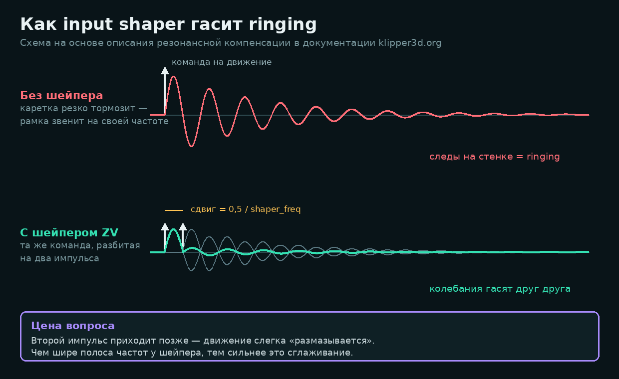
Схема на основе описания резонансной компенсации в документации Klipper
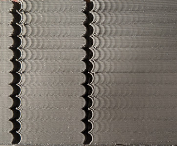
Тестовая печать с ringing. Иллюстрация из документации Klipper
Путь А. Без акселерометра — башня с ускорениями
Печатается ringing_tower.stl: слой 0,2–0,25 мм, 1–2 периметра или ваза, внешние периметры на 80–100 мм/с, минимальное время слоя не больше 3 секунд, динамическое ускорение выключено. Команда:
TUNING_TOWER COMMAND=SET_VELOCITY_LIMIT PARAMETER=ACCEL START=1500 STEP_DELTA=500 STEP_HEIGHT=5
Дальше — линейка или штангенциркуль: измеряем расстояние D (мм) между несколькими колебаниями и считаем их количество N на этом отрезке. Частота:
частота (Гц) = V × N / D
где V — скорость внешнего периметра в мм/с. Считается отдельно для X и Y по меткам на модели.
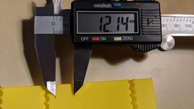
Замер расстояния D между колебаниями. Иллюстрация из документации Klipper
Путь Б. С акселерометром
Klipper работает с ADXL345, MPU-9250, LIS2DW и LIS3DH-совместимыми датчиками. ADXL345 — только SPI, MPU и LIS умеют и SPI, и I²C.
Пример подключения ADXL345 напрямую к Raspberry Pi:
[mcu rpi]
serial: /tmp/klipper_host_mcu

[adxl345]
cs_pin: rpi:None

[resonance_tester]
accel_chip: adxl345
probe_points:
    100, 100, 20
Тот же датчик через RP2040:
[mcu adxl]
serial: /dev/serial/by-id/usb-Klipper_rp2040_<серийник>

[adxl345]
cs_pin: adxl:gpio1
spi_bus: spi0a
axes_map: x,z,y

[resonance_tester]
accel_chip: adxl345
probe_points:
    147, 154, 20
Проводку документация советует делать экранированной витой парой (cat5e и лучше), проверять сопротивление подтяжек I²C (ориентир — от 900 Ом до 1,8 кОм) и подключать экран к земле MCU. Перед подачей питания проверьте распиновку дважды: ошибка убивает датчик.
Проверка связи и шума:
ACCELEROMETER_QUERY
MEASURE_AXES_NOISE
ACCELEROMETER_QUERY должен вернуть три числа, где по вертикальной оси видно ускорение свободного падения — примерно так:
// adxl345 values (x, y, z): 470.719200, 941.438400, 9728.196800
MEASURE_AXES_NOISE в норме даёт значения примерно от 1 до 100.
Значения выше 1000 в MEASURE_AXES_NOISE — это не «шумный датчик, сойдёт». Это либо проблема с питанием и проводкой, либо разбалансированный вентилятор, который трясёт всю раму. Мерить резонансы в таком состоянии бессмысленно: вы снимете спектр вентилятора.
Сам замер (input shaper на время теста должен быть выключен):
TEST_RESONANCES AXIS=X
TEST_RESONANCES AXIS=Y
CSV попадут в /tmp/resonances_x_*.csv и /tmp/resonances_y_*.csv. Обработка:
~/klipper/scripts/calibrate_shaper.py /tmp/resonances_x_*.csv -o /tmp/shaper_calibrate_x.png
~/klipper/scripts/calibrate_shaper.py /tmp/resonances_y_*.csv -o /tmp/shaper_calibrate_y.png
Вывод выглядит так:
Fitted shaper 'mzv' frequency = 34.6 Hz (vibrations = 0.0%, smoothing ~= 0.170)
To avoid too much smoothing with 'mzv', suggested max_accel <= 3500 mm/sec^2
Recommended shaper is mzv @ 34.6 Hz
Автоматический вариант — SHAPER_CALIBRATE (на «качельке» имеет смысл гонять по одной оси: SHAPER_CALIBRATE AXIS=Y), затем SAVE_CONFIG. Результат в конфиге:
[input_shaper]
shaper_freq_x: 57.8
shaper_type_x: zv
shaper_freq_y: 34.6
shaper_type_y: mzv

[printer]
max_accel: 3000
Если тряска при тесте кажется чрезмерной, снизьте accel_per_hz (по умолчанию 75):
[resonance_tester]
accel_chip: adxl345
accel_per_hz: 50
probe_points: ...
Какой шейпер выбирать
| Шейпер | Длительность | Полоса подавления (порог 5 %) | Сглаживание |
|---|---|---|---|
| ZV | 0,5 / freq | — | минимальное |
| MZV | 0,75 / freq | ±4 % от частоты | низкое |
| ZVD | 1 / freq | ±15 % | среднее |
| EI | 1 / freq | ±20 % | среднее |
| 2HUMP_EI | 1,5 / freq | −40…+45 % | высокое |
| 3HUMP_EI | 2 / freq | −50…+60 % | очень высокое |
Логика простая: чем длиннее шейпер, тем шире полоса частот, которую он гасит, и тем сильнее размывает мелкие детали. Скрипт calibrate_shaper.py уже взвешивает этот компромисс, но если сглаживание не устраивает, его можно ограничить явно:
~/klipper/scripts/calibrate_shaper.py /tmp/resonances_x_*.csv -o /tmp/shaper_calibrate_x.png --max_smoothing=0.2
Документация отдельно предупреждает: гонять автокалибровку шейпера часто — например, перед каждой печатью или ежедневно — не стоит. Тестовые прогоны сильно трясут машину, ускоряя износ и ослабляя крепёж. После калибровки имеет смысл пройтись по винтам.
Шаг 7. max_accel: минимум из двух пределов
Последний шаг — и единственный, где SAVE_CONFIG вам не поможет: значение подбирается глазами по тестовой печати.
Пределов два, и брать надо меньший:
- Предел по ringing — максимальное ускорение, при котором следы колебаний ещё приемлемы.
- Предел по сглаживанию — максимальное ускорение, при котором не теряются детали. Индикатор в тестовой модели — зазор 0,15 мм в стенке: чем сильнее сглаживание, тем шире он выглядит.

Тот самый зазор 0,15 мм, по которому оценивают сглаживание. Иллюстрация из документации Klipper
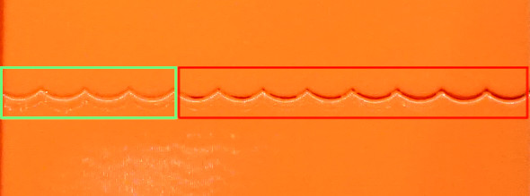
Чем выше ускорение, тем шире выглядит зазор. Иллюстрация из документации Klipper
square_corner_velocity при этом трогать не надо: документация советует оставить значение по умолчанию 5 мм/с, потому что его увеличение добавляет сглаживания ровно там, где мы его только что убирали.
Шпаргалка: полный проход
# 0. проверки
M112 / FIRMWARE_RESTART
QUERY_ENDSTOPS
STEPPER_BUZZ STEPPER=stepper_x

# 2. подача
G91
G1 E50 F60

# 3. нагреватели
PID_CALIBRATE HEATER=extruder TARGET=170
PID_CALIBRATE HEATER=heater_bed TARGET=60
SAVE_CONFIG

# 5. pressure advance
SET_VELOCITY_LIMIT SQUARE_CORNER_VELOCITY=1 ACCEL=500
TUNING_TOWER COMMAND=SET_PRESSURE_ADVANCE PARAMETER=ADVANCE START=0 FACTOR=.005

# 6. резонансы
MEASURE_AXES_NOISE
SHAPER_CALIBRATE
SAVE_CONFIG

# 7. потолок ускорения — руками, по тестовой печати
Возвращаться к началу придётся при любом вмешательстве в механику: замена хотэнда меняет массу каретки и частоту, замена ремня — натяжение, новая поверхность стола — Z-offset. Это не повод калибровать всё заново каждую неделю, но повод помнить, какой шаг вы только что обнулили.
Интересно сравнить реальные цифры: какая у вас shaper_freq по X и Y, на какой кинематике и с каким max_accel в итоге печатаете? И был ли случай, когда после протяжки ремней частота уезжала настолько, что старый шейпер начинал мешать?
Источники
- Klipper, Config checks — Configuration checks - Klipper documentation
- Klipper, Rotation distance — Rotation distance - Klipper documentation
- Klipper, Pressure advance — Pressure advance - Klipper documentation
- Klipper, Resonance compensation — Resonance Compensation - Klipper documentation
- Klipper, Measuring resonances — Measuring Resonances - Klipper documentation
- Klipper, Config reference — Configuration reference - Klipper documentation